Clocking in Microcontroller
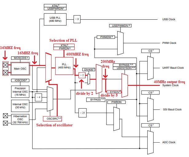
TM4C123GH6PM microcontroller operates on a minimum of 3.125Hz and a maximum of 80MHz clock frequency. Four clock sources are used in the microcontroller. The main clock tree is shown below.
Fig 3.2 Main clock tree for microcontroller
Precision Internal Oscillator (PIOSC):
The PIOSC is a on chip clock source for microcontroller. This oscillator does not required any external component o generate frequency. It provides clock frequency of 16MHz with ±1% accuracy at room temperature. If PIOSC is not used for main system clock it can be used for UART, SSI baud rate generation or ADC clock.
Main Oscillator (MOSC):
The main oscillator is used to provide clock frequencyin two types. For single ended clock crystal is connected to OSC0 pin and for differential clock crystal is connected to OSC0 and OSC1 pin. If the main oscillator is using with PLL then crystal frequency must be 5MHz to 25MHz. If the PLL is not in used then need to connect external crystal which is in frequency range of 4MHz to 25MHz
Low-Frequency Internal Oscillator (LFIOSC):
A Low frequency internal oscillator is used during Deep-Sleep power-saving mode. It gives the frequency output of 30KHz.
Hibernation Module Clock Source:
The Hibernation module is clocked by external 32.768-kHz crystal. This crystal is connected to XOSC0 and XOSC1 pin. Hibernation clock source is used when microcontroller is in deep-sleep mode or hibernation mode to save power.
4.1 Generation of system clock:
Initially, we need to select the main oscillator source. which we have to use. This source will be either an internal precision oscillator or the main oscillator. OSCSRC function is working as a select line for multiplexer for selection of main clock source. If we are using the main oscillator then we need to adjust the frequency of crystal which is connected with OSC0 and 0SC1 pin. Next, we have to select either we have use PLL or directly oscillator frequency we have to use. In the end, the SYSDIV factor is used to manage clock frequency value. SYSDIV function supports value from 1 to 64.
4.1.1 Generation of 40MHz system clock:
For 40MHz clock initially using external 16MHz crystal which is present on the launchpad. This crystal value must be lies between 5MHz to 25MHz. Then the main oscillator will be used to fix the frequency value to 16MHz. To increase the frequency value now PLL will be used. PLL gives an output frequency of 400MHz. internal divider divides this clock by 2 and gives 200MHz clock frequency. Next SYS_DIV_5 function will use be used. It will divide (200 / 5) and give the output frequency of 40 MHz. The generation of the clock is shown in the below figure.
API representation of the same is shown below: SYSCTL_SYSDIV_5 | SYSCTL_USE_PLL
| SYSCTL_OSC_MAIN | SYSCTL_XTAL_16MHZ
4.1.2 Generation of 16MHz system clock:
For the generation of 16MHz clock initially selecting external crystal with the main oscillator, it will the frequency of 16MHz. So now the use of PLL is not required so directly passing through oscillator with a divide function of 1. This will produce the system clock of 16MHz.
API representation of the same is shown below: SYSCTL_SYSDIV_1 | SYSCTL_USE_OSC | SYSCTL_OSC_MAIN |
SYSCTL_XTAL_16MHZ
4.2 Generation of clock for PWM signal:
PWM clock has two sources: Directly using system clock or by using PWMDIV function frequency can be adjusted. Possible values for PWMDIV must be (1, 2, 4, 8, 16, 32, 64) from this value.
4.2.1 Generation of 625KHz PWM clock:
For this, we have to take a system clock frequency of 40MHz. Then by using the PWMDIV_64 function we will get (40MHz /64 ) the output clock frequency of 625KHz. The implementation of the PWM clock is shown below.
API representation of the same is shown below: SYSCTL_PWMDIV_64
4.3 Generation of ADC clock:
ADC module supports the operating clock frequency of 16MHz. ADC module is sourced by PLL source, external crystal connected to main OSC, or precision OSC.
- If PLL is using then the ADC clock is directly generated by dividing 400MHz clock by 25 to get 16MHz.
- If PLL is not using then the ADC clock is directly generated by external 16MHz crystal.
- If external crystal value is not 16MHz then the ADC clock is generated by Precision Internal OSC.
4.4 Generation of USB clock:
USB clock is generated by taking input from main OSC or by using crystal connected to main OSC. PLL gives an output frequency of 480MHz and ÷8 function is used to divide frequency. TM4C123GH6PM supports 5, 6, 8, 10, 12, 16, 18, 20, 24, or 25 MHz frequency for operation.
4.5 UART and SSI baud rate generation:
UART and SSI baud rate clockis generated by taking reference input from the system clock or directly from a precision internal oscillator. By using the internal division circuit value of the clock signal is adjusted . The generation of the baud rate for UART and SSI is explained in their respective sections.


Comments
Post a Comment